Sine Reduction
Product Overview
Sine Reduction test runs so that the Digital Signal Analyzer (DSA) is synchronized to a Vibration Control System (VCS). By doing this, more processing channels can be arranged on the Sine Reduction system, and work simultaneously with the swept sine test. COLA (Constant Output Level Adaptor) signal is crucial for this type of test. Two instruments are synchronized through controller’s COLA output signal. The COLA signal is a constant voltage sine wave which frequency tracks the Drive signal frequency during the Sine Control test. Sine Reduction test is widely used for the satellite testing, and typically, hundreds of input channels are required.
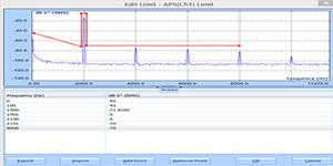
Alarm/Abort and Data Recording
The Sine Reduction system offers added safety with the limit feature from specific channels. Both the alarm and abort limits can be set for certain input channels, at the locations where vibration level needs to be monitored. With this feature, more channels could be set up and used to initiate alarms or aborts event, when any channel exceeds specified limits. With the Sine Reduction system monitors the Sine Control test, alarms may be displayed on the screen with the visual and audio means along with the information of corresponding channel IDs. With the equipped digit output channel connected to the controller’s emergency stop switch, a Sine control test can be automatically stopped in case any channel exceeds its abort limit.
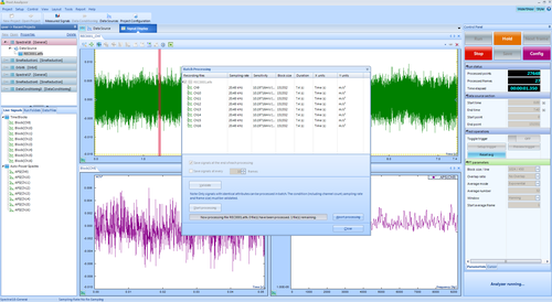
Time stream data can be recorded while the Sine Reduction test is running. This is critical for satellite testing. The recorded data can be reanalyzed with the Sine Reduction or other Analysis module, so that to understand the vibrations applied to the device under test.
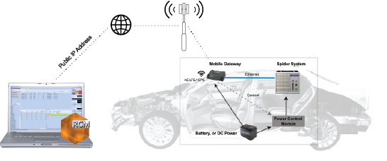
Typical Test
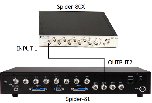
As illustrated in the below picture, a typical Sine Reduction test system consists of a Vibration Controller and a Dynamic Signal Analyzer. The Spider-81 VCS provides eight channels of input to run the Sine Control. By connecting its Output 2 (with the COLA signal) to the Channel 1 input of a Spider-80X DSA module running Sine Reduction, the combined system provides 15 input channels total running with same tracking filters in perfect synchronization. With more modules to the Spider-80X, the input channel count will be increased per user requirement.
Configuration on EDM
To configure the COLA output channel on a Spider Sine controller, Go to Config -> Miscellaneous -> Second Output tab and set it to COLA Type 1: Constant Amplitude Sine; set amplitude to 1 V. In case of controller by other vendor is used, make sure its COLA channel is set to sweep at the Drive frequency with a constant voltage level.
To set up the Sine Reduction test on analyzer side, first create a test using EDM. Go to Input Channels table to set the channel 1 Channel Type to COLA. Each Sine Reduction test requires one COLA channel. In this example, the first input channel is set as COLA channel. Though any one of the inputs can be COLA input channel. Sine Reduction parameters can be found in the Test Parameters tab under Test Configuration. All parameters should match those setting on Sine Controller. The COLA Amplitude is determined by the COLA output setting of the Sine Controller. The Low Frequency and High Frequency parameters must match the test profile of the sine controller. The sine controller can be started before or after starting this DSA Sine Reduction test.
History of Data Reduction Function & How it Has Changed
The data reduction function was widely used in the old days when a vibration controller has few input channels while it is still required to acquire and analyze hundreds channels of data. Two decades ago, most vibration controllers can only run up to 4 to 8 input channels. To have more input channels for a large test, the user has to connect another data acquisition system with large input channels, which is the one used for so called “data reduction”, to acquire the data while the controller is operated with small input channels.
When data reduction is executed in a Sine data acquisition system, the swept spectra generated by tracking filters will be recorded. In a Random data acquisition system, only the PSD generated by FFT are recorded. No original time streams are recorded.
With the new implementation of Spider system and particularly with its network structure, the data reduction function is really not needed because our vibration controller can extend its input channels to hundreds (256, 512 etc). The user can use some of the input channels as control channels, the rest channels can be set as monitoring, limiting, recording or abort channels at the same time. Many other vendors also has this philosophy in its implementation.
In a typical Sine test, the old approach is using COLA channel to transfer the sweeping frequency information from the controller to the data reduction system. In the new Spider system, the frequency information is passed from the controller to all acquisition modules through Ethernet.
The powerful new design of Spider in the controller replaced the old concept, data reduction. However, if the user still prefers to use the concept of “data reduction” due to legacy regulatory requirement, Crystal Instruments still provides such functions as mentioned above.
Frequency Response Function (FRF)
A common application of dynamic signal analyzers is the measurement...View Details
Octave Analysis and Sound Level Meter (SLM)
Acoustics measurements are performed for a variety of reasons, including:...View Details
Time Waveform Recording
While many manufacturers provide long term data recording functions on...View DetailsShock Response Spectrum Analysis
A Shock Response Spectrum (SRS) is a graphical presentation of...View Details
Automated Production Testing
Automated production testing is critical in today’s competitive manufacturing environment....View Details

Remote Condition Monitoring Software
Remote Condition Monitoring (RCM) by Crystal Instruments is designed for...View Details
Vibration Visualization (DSA)
It is difficult to imagine the actual vibration level and...View Details
EDM Post Analyzer Software
The Post Analyzer application is used for the post processing...View Details

Precision Starts Here