Mix Mode Vibration Testing – SOR & ROR
Product Overview
Some vibration environments are characterized by quasi-periodic excitation from reciprocating or rotating machines (e.g. rotor blades, propellers, or pistons). These can be simulated as one or more high-level narrowband or sinusoidal vibration components superimposed on a low-level broadband random profile. These are called mixed-mode random tests.
There are two types of mixed-mode random tests supported in EDM: Sine on Random (SoR) and Random on Random (RoR). In each of these test types, an additional vibration profile is placed on top of the regular broadband random profile. In Sine on Random, this additional profile consists of one or more sine tones that sweep through a specified frequency range. The random profile may represent a base excitation or background noise level, and the sine tones represent strong single-frequency excitations.
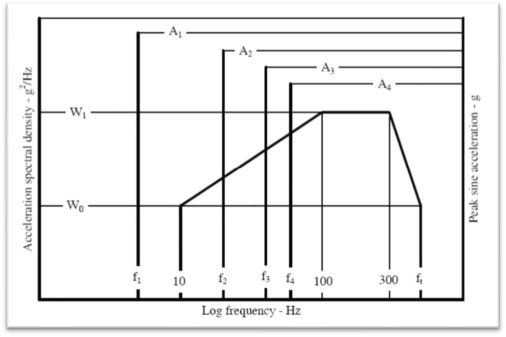
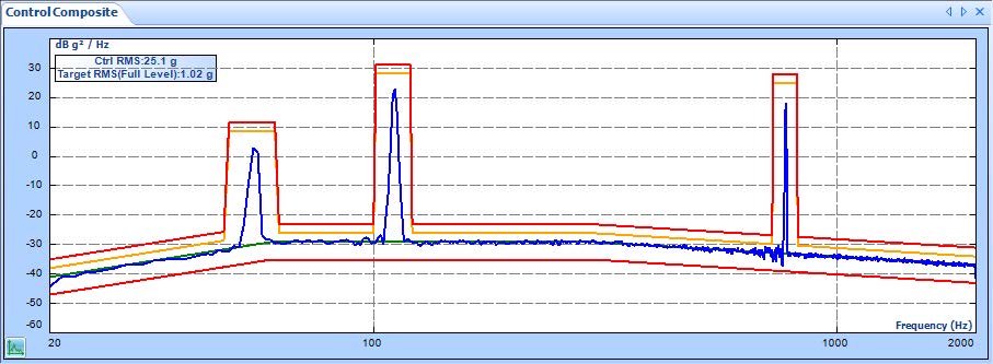
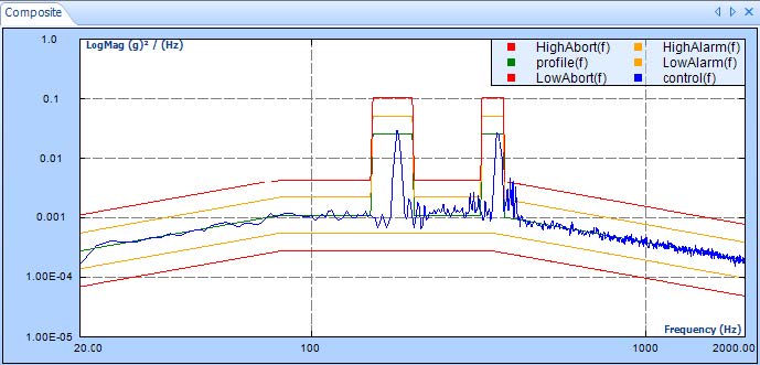
A typical profile of SoR described in MIL-STD-810F is shown below. Note that the random broadband profile is defined in units of Power Spectral Density, or g2/Hz, while the sine components are specified as amplitudes in units of g.

Product Resources
Key Features

-
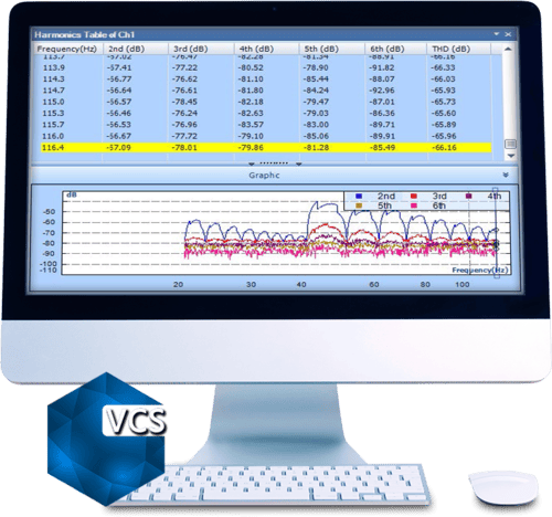
Sweeping Modes: sine tones can either be individually configured with sweeping speeds and schedules (Free Sweep mode), or jointly defined as harmonics of the first primary tone (Harmonic mode)
-
Number of Sine Tones (SoR): 1 – 12 in free-sweeping mode; 1 – 20 in harmonic mode, up to 32 when RoR is disabled
-
Number of Bands (RoR): 1 – 12, up to 32 when SoR is disabled.
-
Operation Controls (SoR): Tone On and Tone Off controlled by run schedule, external events, or user commands
-
Operation Controls (RoR): Band On and Band Off controlled by run schedule, external events or user commands
-
Supports up to 512 input channels
Multi-Resolution Feature
The Spider controller’s unique Multi-Resolution feature is a perfect solution for displaying low frequency sine tones that are hard to display due to an inadequate frequency resolution.
Traditionally, providing a better resolution for low frequency sine tones required increasing the block size (also known as “frame size”), resulting in more data collection time and slower reactions to hitting abort limits.
On the other hand, Multi-Resolution applies a custom 8x sharper resolution to only the low frequency part of the spectrum, while running the rest of the spectrum with the original resolution.
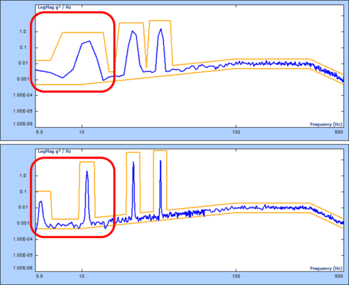
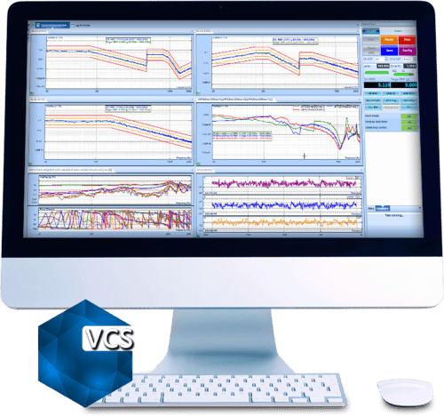
SoR profile (MIL-STD-810H) without and with Multi-Resolution Continuous Data Recording
During vibration control, all measurement input and drive signals can continuously record to a Spider-NAS or the internal storage residing in each front-end. Users can view and analyze data files with Crystal Instruments Post Analyzer. The variable sampling rate can be enabled to simultaneously record slow-change signals together with high speed vibration data.
-
Drive Notching and Limiting
Limiting is applied to control or monitor channels. Three types of limiting are available in Random Control: frequency domain, time domain, and advanced limit. Frequency domain limiting is spectrum limiting. Limit types are notching limit, abort limit, and alarm limit.
Time domain limiting compares raw data or the RMS value of input channels to the high limit. The occurrence of exceeding the high limit is one of the system events to which desirable actions can be added.
Advanced limit includes summed channel notching and vector notching. A summed virtual channel is defined as the weighted average of raw time stream signals from multiple input channels. The notch profile of a summed channel is defined in the frequency domain.
A vector RRS signal is defined as the vector sum of raw time stream signals from 3 input channels. The notch profile of a vector RRS signal is defined in the frequency domain as well.
Supports up to 128 notching/limiting channels out of 512 input channels.
Hardware
- Spider-81 Premium Vibration Controller
- Spider-81B Basic Vibration Controller
- Spider-80X High Channel Vibration Controller – Scale up to 512 Channels
- Spider-80Xi High Channel Vibration Controller – Compact, handheld high channel system
- Spider-80M – MIMO Vibration Control System
Software
- Random Vibration Control
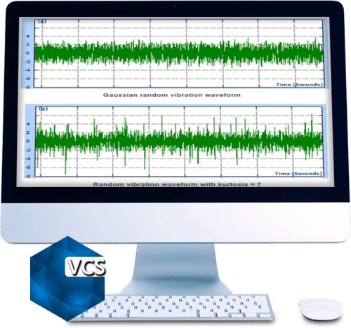
- Kurtosis Control for Vibration Testing
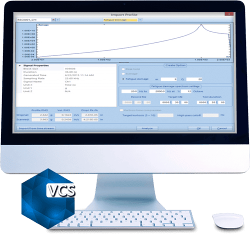
- Fatigue Damage Spectrum in Random Vibration Testing
Monitoring Through EDM Cloud
All tests in EDM-VCS support status checks through EDM Cloud. With EDM Cloud support, users can set up any VCS test to upload live data or run logs for completed tests to a cloud storage space provided by Crystal Instruments, where data is securely stored in the user’s account.
The EDM Cloud website is located at https://cloud.go-ci.com. Users can access EDM Cloud from anywhere in the world to check the status of past and current tests. A secure login flow ensures the status can only be checked by authorized personnel with proper credentials. Multiple logins for accessing the same Cloud account is available.
AutoShock-II: Automated Shock Test System
The AutoShock-II ™ is a fully automated series of shock...View Details
SD-Series: Mechanical Shock Machines
L.A.B. Equipment’s SD-Series mechanical shock machines provide precision testing for...View Details
Test Lab Professional™ Vibration v6 – USB
Test Lab Professional™ (TLP) is specifically designed to support the...View Details
Random Vibration Testing
The Random Vibration Control System provides precise, real-time, multi-channel control...View Details
Mix Mode Vibration Testing – SOR & ROR
Some vibration environments are characterized by quasi-periodic excitation from reciprocating...View Details
Swept Sine Vibration Testing
The Spider Swept Sine Vibration Control System provides precise, real-time,...View Details
Resonance Search and Dwell Test
The RSTD feature occurs in two phases. First, resonant frequencies...View Details
Multi-Sine Test
Multi-Sine Control allows for simultaneously sweeping multiple sine tones, helping...View Details
Shock Response Spectrum Synthesis & Control
The Shock Response Spectrum (SRS) vibration control package provides controls...View Details
Transient Time History Control
Generate or import transient time waveforms into EDM VCS for...View Details
Classic Shock Control
The Classic Shock vibration control feature provides precise, real-time, multi-channel...View Details
Transient Random Control
Transient Random Control drives a series of transient pulses to...View Details
Earthquake Testing Control
Vibration Tests for Seismic Qualification The earthquake testing control package...View Details

Multiple Shaker Control
EDM Multi-Shaker Control (MSC) is a software option included in...View Details
Vibration Visualization (VCS)
The 3D Model Reconstruction software produces 3D geometric models of...View Details
Multi-Resolution Function For Random Vibration Control
An Innovative Approach to Improve the Control Accuracy in the...View Details


MIMO Vibration Control
Multiple-Input Multiple-Output Vibration Control Software MIMO Testing has gained a...View DetailsFatigue Damage Spectrum
Fatigue Damage Spectrum (FDS) allows users to compare the potential...View DetailsMIMO Random Vibration Control
Multiple-Input Multiple-Output Random VCS The MIMO Random Control System provides...View Details
MIMO Sine Vibration Control
Multiple-Input Multiple-Output Sine VCS The MIMO Sine Control System provides...View Details
MIMO Classic Shock Vibration Control
Multiple-Input Multiple-Output Shock VCS The Spider MIMO Classic Shock Vibration...View Details
MIMO Transient Time History
Multiple-Input Multiple-Output TTH VCS Using template based importing tools, time...View DetailsMIMO Shock Response Spectrum
Multiple-Input Multiple-Output SRS VCS The Shock Response Spectrum vibration control...View Details
MIMO Time Waveform Replication
Multiple-Input Multiple-Output TWR Vibration Control MIMO Time Waveform Replication (TWR)...View Details
Precision Starts Here