
Real Time Digital Filters
Product Overview
Real Time Digital Filters can be used to filter a measured signal in real time. Filter characteristics can be defined by the user to meet the requirements of a specific application. Real-time digital filters are applied in the data conditioning phase. The filters are designed with a graphic design tool and then uploaded to the front-end for real-time calculation. The graphic design tool defines the filter performance vertical axis with a dB scale. The horizontal axis is defined as relative frequency.
For example, a user might want to look at the energy distribution for a specific band of frequencies over time instead of for the entire frequency spectrum. This can be done by creating a band-pass filter and then applying an RMS estimator to the output of the filter.
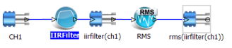
The figure below shows a graphical representation of the process used to define a real time filter in the EDM software. The icon on the left, CH1 represents the native measured time stream. It is connected to an IIR Filter which computes a signal named iirfilter (ch1) which is connected to an RMS estimator. The output of the RMS estimator is a signal named rms(iirfilter(ch1)).

Additional Information
The Real Time Digital Filters option includes three types of digital filters: Finite Impulse Response (FIR), Infinite Impulse Response (IIR) and decimation filters. For the FIR and IIR filters you can specify: low-pass, high-pass, band-pass or band-stop filters with several different methods.
This chapter first explains some filter design theory and then introduces filter operations within the EDM and the Spider hardware.
The goal of filter design is to calculate a series of filter coefficients based on user specified criteria. The criteria are often described by following variables:
-
Number of filter coefficients: this is also known as the order of the filter. The filter order defines how many coefficients are required to define the filter. A lower order filter consists has fewer coefficients. A low order filter responds faster than a higher order filter so there are fewer time lags between the input and output of the filter.
-
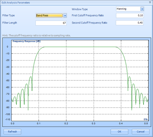
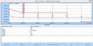
Cutoff frequencies: For low-pass or high-pass filters, only one cutoff frequency is needed. Band-pass or band-stop filters require two cutoff frequencies to fully define the filter shape. Figure 172 shows a typical band-pass filter design with the two cutoff frequencies set to approximately 0.1 and 0.2 Hz.
-
Stop-Band Attenuation: This specification defines how much of the input signal is cut out of the output at the rejected frequencies. In theory, the higher the attenuation the better the filter. The stop-band attenuation is greater than 40 dB as seen from the highest side lobe just below 0.25 Hz.
-
Pass-Band Ripple: Ripple is an unavoidable characteristic if a digital filter. It refers to the fluctuation in the filter shape outside the transition frequencies. If a very flat filter is required then it can be specified by choosing a very low ripple. In Figure 172, the ripple is seen in the stop band but no ripple is evident in the pass-band. Ideally the pass-band should be very flat and some ripple is tolerable in the stop-band.
-
Width of transition bands: This refers to the filter shape between a band-pass and a stop-band region. Ideally this transition band should be very small. However, a very narrow transitional band requires a higher order filter which affects the filter response time and can also affect ripple. The transition bands are between 0.05 to 0.1 and 0.2 to 0.25.
In most cases filter design includes making trade offs between minimizing the filter order, ripple, transition band-width, and response time. Not all can be satisfied at the same time. Filter design can be an iterative process and experience is helpful.
-
Frequency Response Function (FRF)
A common application of dynamic signal analyzers is the measurement...View Details
Octave Analysis and Sound Level Meter (SLM)
Acoustics measurements are performed for a variety of reasons, including:...View Details
Time Waveform Recording
While many manufacturers provide long term data recording functions on...View DetailsShock Response Spectrum Analysis
A Shock Response Spectrum (SRS) is a graphical presentation of...View Details
Automated Production Testing
Automated production testing is critical in today’s competitive manufacturing environment....View Details

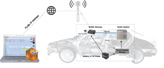
Remote Condition Monitoring Software
Remote Condition Monitoring (RCM) by Crystal Instruments is designed for...View Details
Vibration Visualization (DSA)
It is difficult to imagine the actual vibration level and...View Details
EDM Post Analyzer Software
The Post Analyzer application is used for the post processing...View Details
Precision Starts Here