Time Waveform Replication
Product Overview
TWR allows for measuring your own time vibration data and playing it back on a shaker. Any arbitrary number of time profiles can be run on a defined schedule, duplicating long waveforms as precisely as they were recorded. Users can enable up to 8 channels for control and time data recording on the master front-end, and up to 512 total channels when including a system of slave front-ends.
Product Resources
Key Features
- Unique Algorithm
Crystal Instruments invented a new algorithm that can faithfully duplicate any long control time signal continuously on a shaker system. This algorithm convolves the system transfer function and the target profile in time domain and then creates a continuous drive signal. On the screen, the target profile and the actual control waveforms are displayed together and can be recorded continuously. - Compatible with Crystal Instruments Data Acquisition Systems
The time waveform signals recorded by a Crystal Instruments data acquisition system (either a CoCo-80X or a Spider-80X) can be directly applied to time waveform (TWR) vibration control. -
Continuous Data Recording
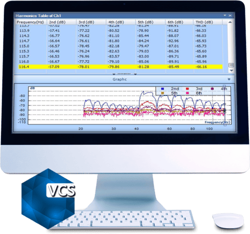
During vibration control, all measurement input and drive signals can continuously record to a Spider-NAS or the internal storage residing in each front-end. Users can view and analyze data files with Crystal Instruments Post Analyzer. The variable sampling rate can be enabled to simultaneously record slow-change signals together with high speed vibration data.
Time Waveform Replication
- Number of Waveform Profiles: Infinite number of Waveform recordings (subject to the available flash memory) is simultaneously supplied to automatically run one after the other on the test specimen.
- Maximum Number of Points: all internal flash memory space is used for storing profile data (currently 3.7 GB), which corresponds to approximately 1 billion data points. At a sampling rate of 200 samples/sec. It can replicate a waveform of about 50 days.
- Maximum Frequency Range: waveforms of up to 18 kHz (fa) can be replicated.
- Maximum Sampling Rate of Data: users can import waveforms of any sampling rate up to 102.4kHz into the Waveform Editor tool and convert them to a suitable frequency range.
Waveform Editor
- Editing: cut, paste, rescale, fill in, taper end points, apply windows, decimate
- Displacement Compensation: brick-wall high pass filter, high pass filter, DC removal, or disabled
- Compensation Template: high pass filter, low pass filter, band pass filter, acceleration DC removal, velocity DC removal.
- Signal View: time waveform of acceleration, velocity, and displacement; FFT spectra; shaker limits; histogram
- Editing Redo: allows the user to redo a previous editing
- Window: half sine, Hann, triangle
- Unique Algorithm
Options
- Line number for spectral analysis sets the number of spectral lines. More lines increase the resolution of frequency data.
- Bin Number sets the resolution of histogram data.
- Profile Quantity sets the quantity as acceleration, velocity, displacement, or voltage
- Undo Max. Step sets the number of cached operations for the Undo command
- Start Average Frame sets the starting frame of the average.
Videos
Abort Limits
TWR abort limits are similar to the abort lines in Shock and are defined in the time domain. If the level of the control signal, within the vicinity of the waveform output, falls outside these limits then an abort event is triggered.
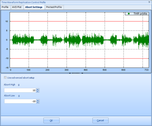
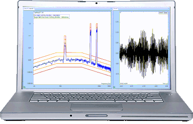
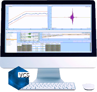
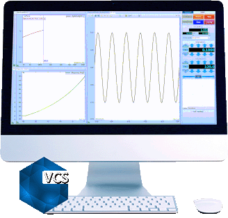
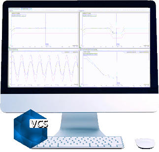
Time Waveform Replication Control Profile
The top of the window shows an acceleration waveform in green. The abort limits are red lines.
The bottom pane has the abort high and low limits which can be set by the user. The user also has options to define different abort limits at different points of time of the time domain waveform. Further details about the different settings available for abort settings are listed in the “Editing Profile and Abort Settings” section below.
Hardware
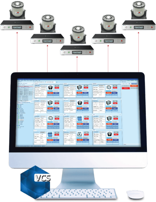
A Spider system can consist of one or more Spider hardware front-ends. The user constructs the system by combining Spider front-ends detected on the same LAN. The software validates and displays hardware attributes of each Spider front-end. The following hardware is supported by EDM VCS software for vibration control, monitoring, and data acquisition.
- Spider-81 Premium Vibration Controller
- Spider-81B Basic Vibration Controller
- Spider-80X High Channel Vibration Controller – Scale up to 512 Channels
- Spider-80Xi High Channel Vibration Controller – Compact, handheld high channel system
- Spider-80M MIMO Vibration Control System
- Spider-80SG General Data Acquisition Device with Strain Measurement
Software
Monitoring Through EDM Cloud
All tests in EDM-VCS support status checks through EDM Cloud. With EDM Cloud support, users can set up any VCS test to upload live data or run logs for completed tests to a cloud storage space provided by Crystal Instruments, where data is securely stored in the user’s account.
The EDM Cloud website is located at https://cloud.go-ci.com. Users can access EDM Cloud from anywhere in the world to check the status of past and current tests. A secure login flow ensures the status can only be checked by authorized personnel with proper credentials. Multiple logins for accessing the same Cloud account is available
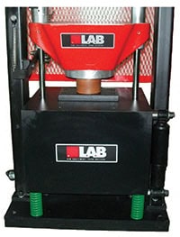
AutoShock-II: Automated Shock Test System
The AutoShock-II ™ is a fully automated series of shock...View Details
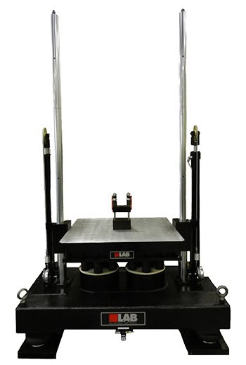
SD-Series: Mechanical Shock Machines
L.A.B. Equipment’s SD-Series mechanical shock machines provide precision testing for...View Details
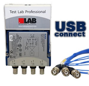
Test Lab Professional™ Vibration v6 – USB
Test Lab Professional™ (TLP) is specifically designed to support the...View Details
Random Vibration Testing
The Random Vibration Control System provides precise, real-time, multi-channel control...View Details
Mix Mode Vibration Testing – SOR & ROR
Some vibration environments are characterized by quasi-periodic excitation from reciprocating...View Details
Swept Sine Vibration Testing
The Spider Swept Sine Vibration Control System provides precise, real-time,...View Details
Resonance Search and Dwell Test
The RSTD feature occurs in two phases. First, resonant frequencies...View Details
Multi-Sine Test
Multi-Sine Control allows for simultaneously sweeping multiple sine tones, helping...View Details
Shock Response Spectrum Synthesis & Control
The Shock Response Spectrum (SRS) vibration control package provides controls...View Details
Transient Time History Control
Generate or import transient time waveforms into EDM VCS for...View Details
Classic Shock Control
The Classic Shock vibration control feature provides precise, real-time, multi-channel...View Details
Transient Random Control
Transient Random Control drives a series of transient pulses to...View Details
Earthquake Testing Control
Vibration Tests for Seismic Qualification The earthquake testing control package...View Details

Multiple Shaker Control
EDM Multi-Shaker Control (MSC) is a software option included in...View Details
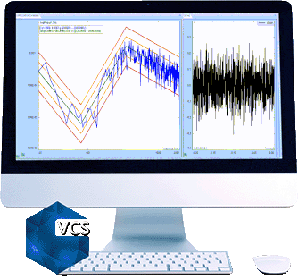
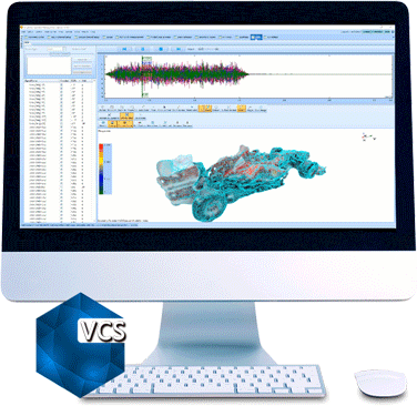
Vibration Visualization (VCS)
The 3D Model Reconstruction software produces 3D geometric models of...View Details
Multi-Resolution Function For Random Vibration Control
An Innovative Approach to Improve the Control Accuracy in the...View Details


MIMO Vibration Control
Multiple-Input Multiple-Output Vibration Control Software MIMO Testing has gained a...View DetailsFatigue Damage Spectrum
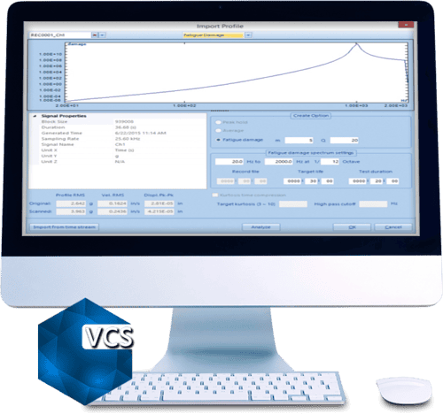
Fatigue Damage Spectrum (FDS) allows users to compare the potential...View DetailsMIMO Random Vibration Control
Multiple-Input Multiple-Output Random VCS The MIMO Random Control System provides...View Details
MIMO Sine Vibration Control
Multiple-Input Multiple-Output Sine VCS The MIMO Sine Control System provides...View Details
MIMO Classic Shock Vibration Control
Multiple-Input Multiple-Output Shock VCS The Spider MIMO Classic Shock Vibration...View Details
MIMO Transient Time History
Multiple-Input Multiple-Output TTH VCS Using template based importing tools, time...View DetailsMIMO Shock Response Spectrum
Multiple-Input Multiple-Output SRS VCS The Shock Response Spectrum vibration control...View Details
MIMO Time Waveform Replication
Multiple-Input Multiple-Output TWR Vibration Control MIMO Time Waveform Replication (TWR)...View Details

Precision Starts Here